
ECU Diagnostics Beyond the Scan Tool: Bench Testing a SYM Citycom 300i ECU
A 2009 SYM Citycom 300i scooter recently came into our workshop with an unusual fault. The scooter had been stolen and recovered after an attempted hotwire. Although the engine would crank normally, it would produce only one spark before the ignition stopped completely. At the same time, the fuel pump would stop priming until power to the ECU was disconnected and restored.
Because the wiring had already been checked and the ignition coil could produce a spark during separate testing, attention turned to the KEIHIN engine ECU.
Building a Controlled Test Bench
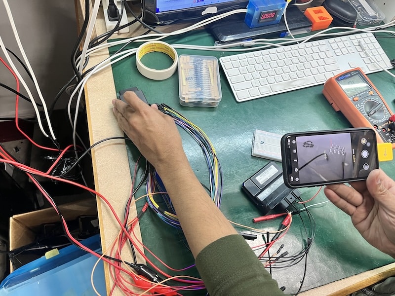
Rather than connecting the ECU straight to vehicle components, we created a controlled bench-testing setup using a breadboard, resistors, a current-limited power supply and a multimeter.
The ECU was first checked for short circuits before applying power. Once we were satisfied there were no obvious shorts, we powered the ECU on the bench and monitored its basic operating conditions.
The ECU drew approximately 0.08 A, while its internal sensor reference supply remained stable at around 5.03 V. This told us the ECU’s primary power and voltage-regulation circuits were operating.
The next challenge was testing the outputs safely.

Using Resistors to Simulate ECU Loads
An ECU normally controls components such as the fuel-pump relay, fuel injector and ignition coil. Connecting these components directly during early diagnosis can introduce unnecessary risk, so we used resistors as dummy loads.
Using the breadboard, we connected known resistance values between the 12 V supply and individual ECU outputs. This allowed us to observe whether each internal driver could correctly pull the circuit low and then release it.
The fuel-pump output behaved as expected. When ignition power was switched on, the ECU briefly activated the fuel-pump circuit before switching it back off.
The ignition output was particularly interesting.
With a light load, its voltage initially appeared unusual. We therefore progressively changed the resistor values to place a controlled but higher load on the circuit. With a 100 Ω dummy load, the ignition output successfully switched approximately 0.1 A, briefly pulling the circuit to ground before releasing it back to 12 V.
This demonstrated something important: the ignition driver was not simply shorted or permanently stuck on.


The Math Behind It
• The Resistance: Four 500-ohm paths in parallel brings the total network resistance down to exactly 100 ohms (500 Ω / 4).
• The Power Rating: With 20 identical resistors, the total load is split 20 ways. If your circuit pushes the full 5W, each resistor handles exactly 0.25W, running right at their rated power limit.
If you were paying attention so far, you would be asking why are we complicating our life with 20 resistors instead of using one 100 Ω load?
The truth is, you absolutely could use a single resistor of the correct resistance. The reason to use many resistors is usually power handling, not resistance.
For example, if you need a 100 Ω load that must dissipate 5 W:
- One 100 Ω, 0.25 W resistor would overheat and likely fail.
- One 100 Ω, 5 W resistor could theoretically do the job.
- In practice, you’d often choose something like a 100 Ω, 10 W resistor to give thermal headroom.
- Or you can combine many smaller resistors so their individual power ratings add up.
We simply did not have 100 Ω 5w or 10w resistor in our workshop at the time 🙂
Watching for Heat with a Thermal Camera
Electrical measurements only tell part of the story.
While powering and loading the ECU, we also used a thermal camera to monitor the board for abnormal heat signatures.
This is particularly useful when diagnosing control modules because a damaged transistor, regulator, protection diode or internal short can sometimes reveal itself through excessive heating before it becomes obvious through voltage measurements alone.
By applying controlled loads rather than immediately connecting the full ignition coil, we could safely monitor how the ECU responded while watching for components heating abnormally.
Why This Type of Testing Matters
An ignition coil is an inductive load and can draw several amps during normal operation. A driver transistor can sometimes work perfectly when switching a small test load but fail when connected to the real coil.
That means this ECU cannot simply be labelled “good” or “bad” based on a continuity test.
Our testing established that:
The ECU powers on normally.
The internal 5 V supply is stable.
There are no obvious hard shorts.
The fuel-pump driver operates.
The ignition output is capable of switching a controlled load.
The ignition driver is not permanently shorted.
Further investigation is required to determine whether the ignition circuit fails only under the much heavier real-world ignition-coil load.
The next stage is component-level investigation of the ignition-driver circuit, including the power transistor, driver circuitry, current-sensing components and transient-protection circuitry.
Cases like this are a good example of why ECU diagnosis often requires more than simply reading fault codes. By combining breadboard testing, calculated dummy loads, current monitoring, thermal imaging and component-level electronics knowledge, we can investigate how a module actually behaves before deciding which components need repair.
You are reading this because you have an ECU with some sort of issue? Contact us now